Welcome to my build log for my Velocity XL/RG-5. As I complete the steps in construction of the aircraft, I will try to post entries, with pictures, to this log. The postings will appear in reverse chronological order, but also be cross-referenced by aircraft subsystem. Feel free to comment or contact me.
Selling the Kit
I have come to the realization that even if I worked on the Velocity build full time, I would still be approaching 70 years old when it is finally usable as an aircraft for traveling. With so many things going on – aging parents, home upkeep, keeping pace with entropy, it is not possible for me to spend the quality time that the Velocity build requires and deserves. So I have decided to sell the kit, hopefully to someone who can appreciate the work that I have done, and who can finish the airplane and fly it and enjoy it the way it was meant to.
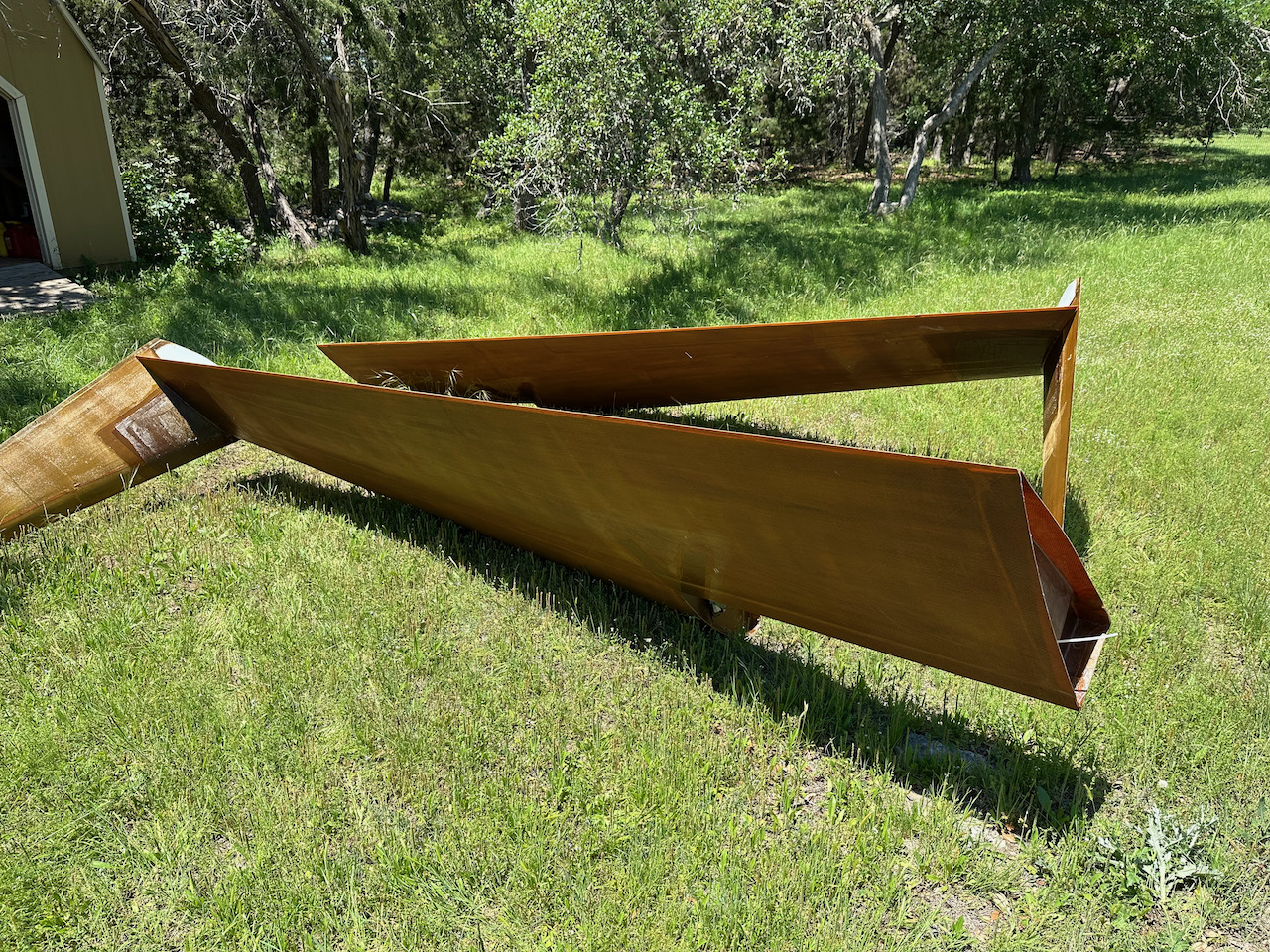
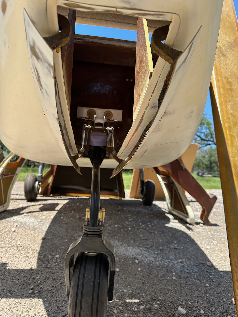
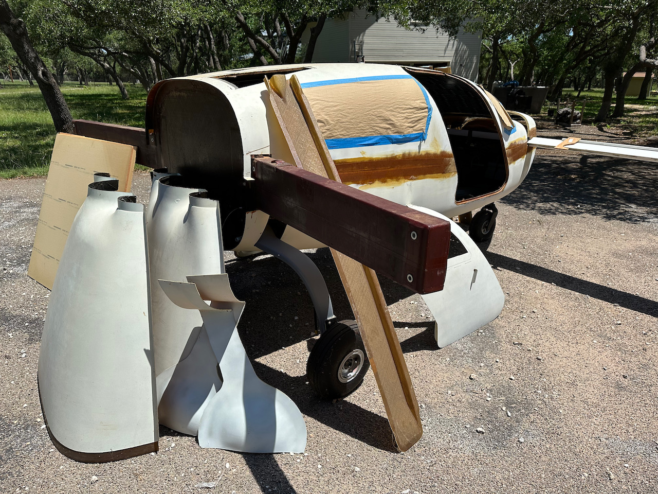
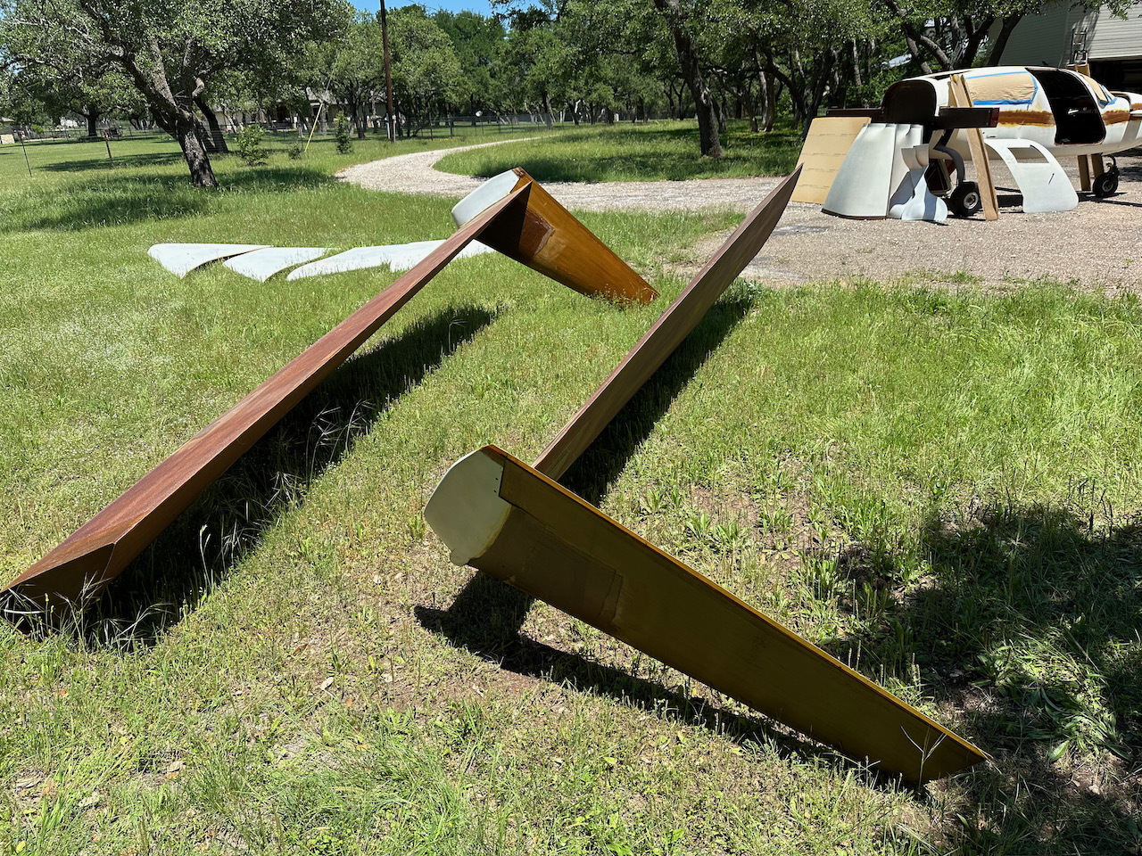
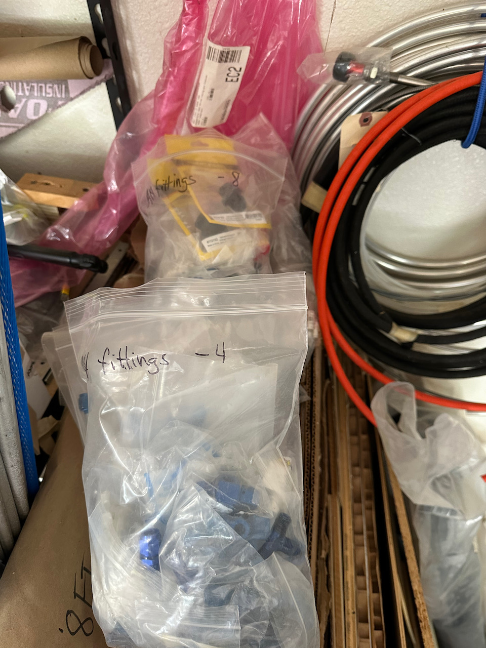
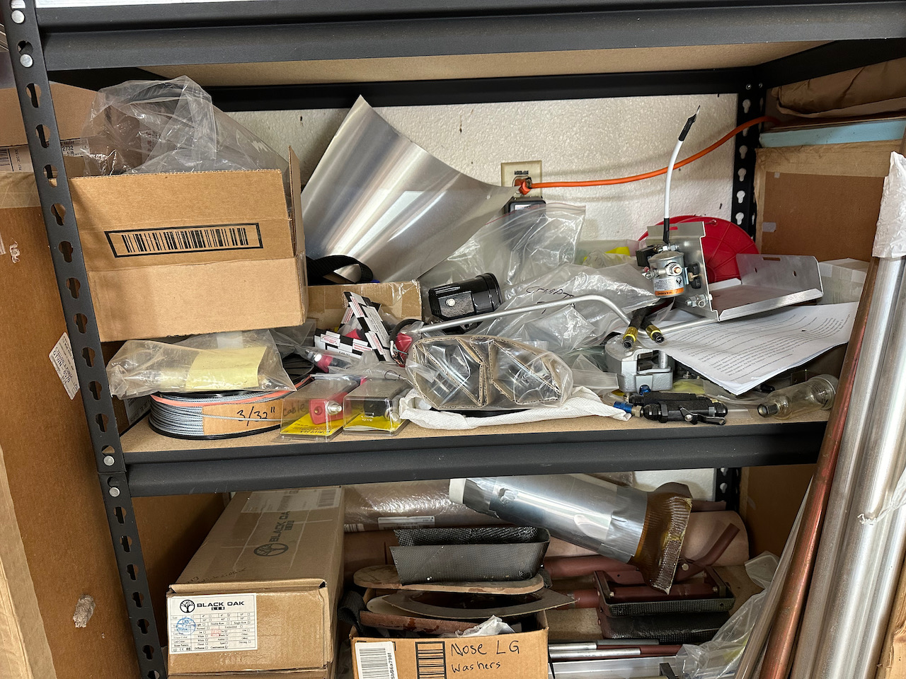
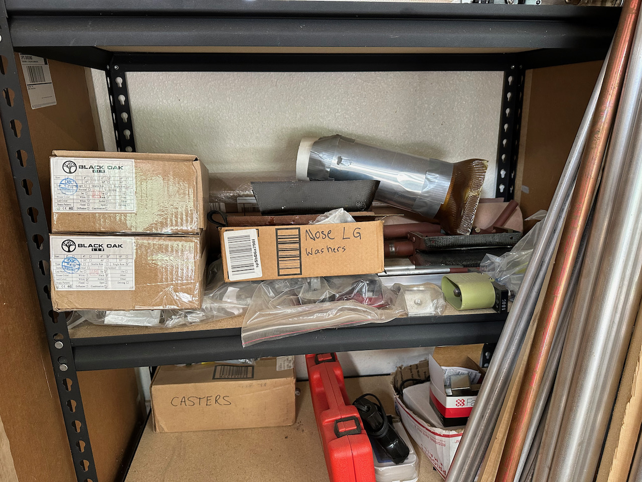
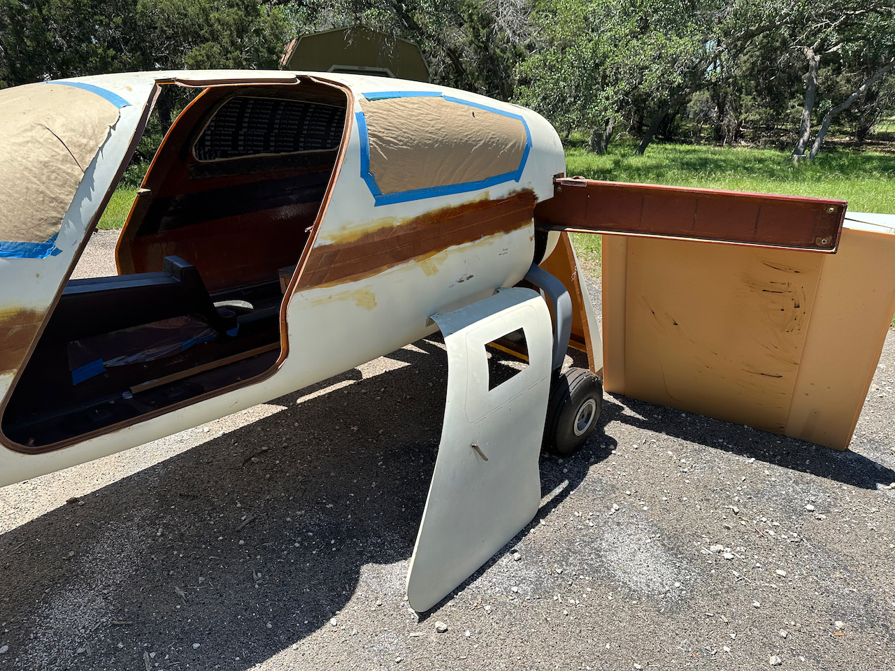
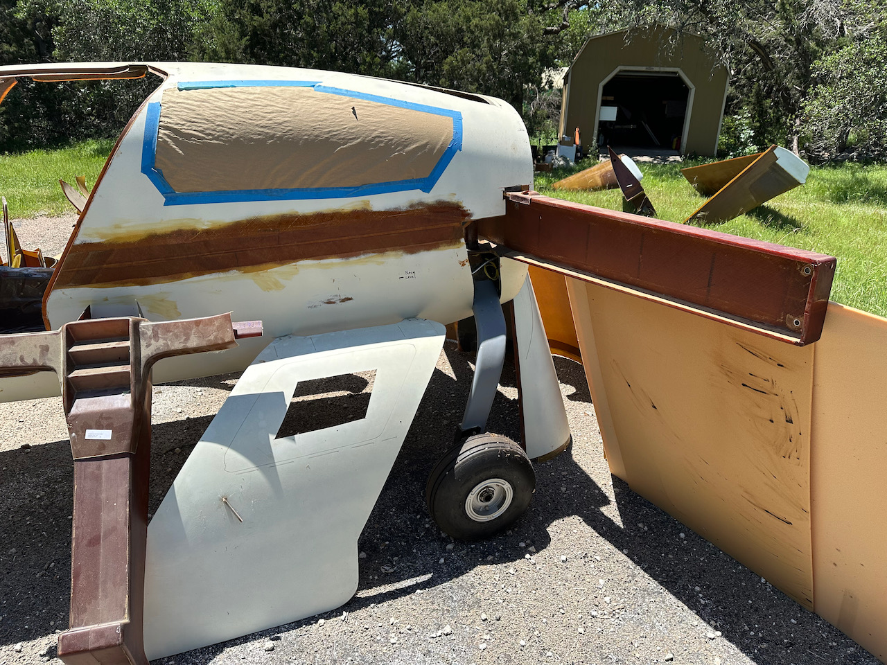
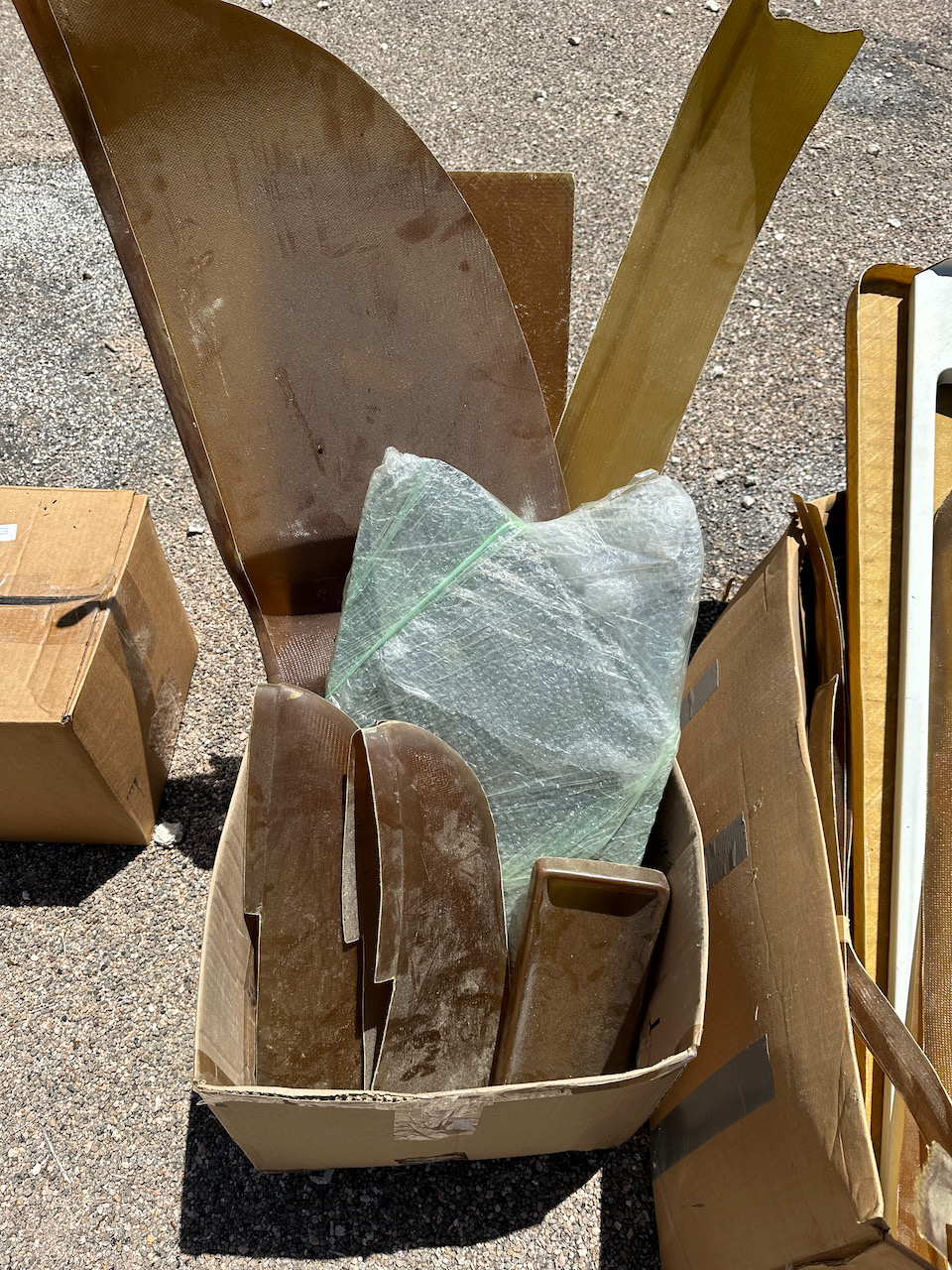
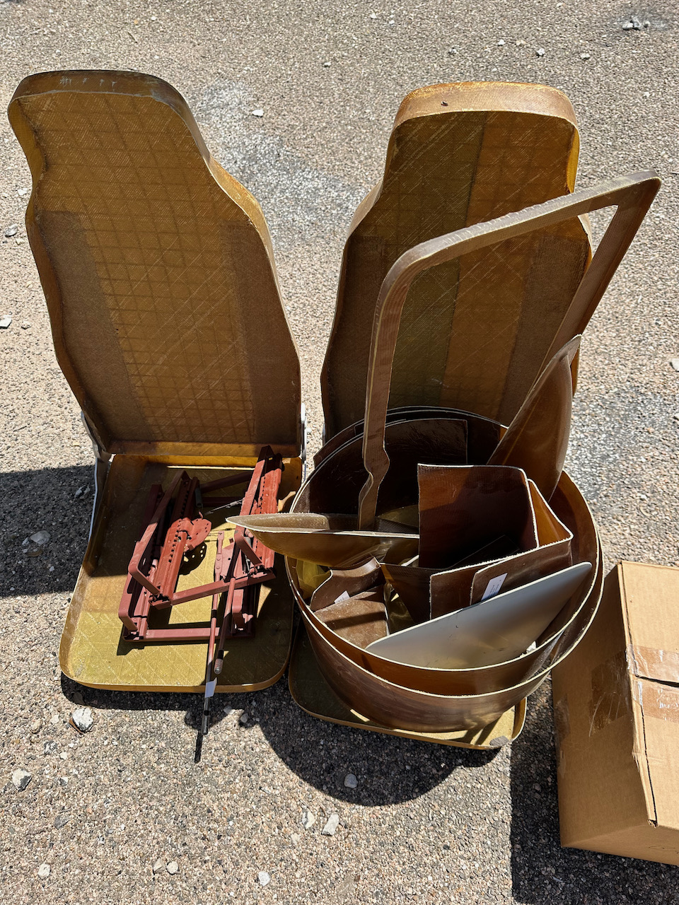
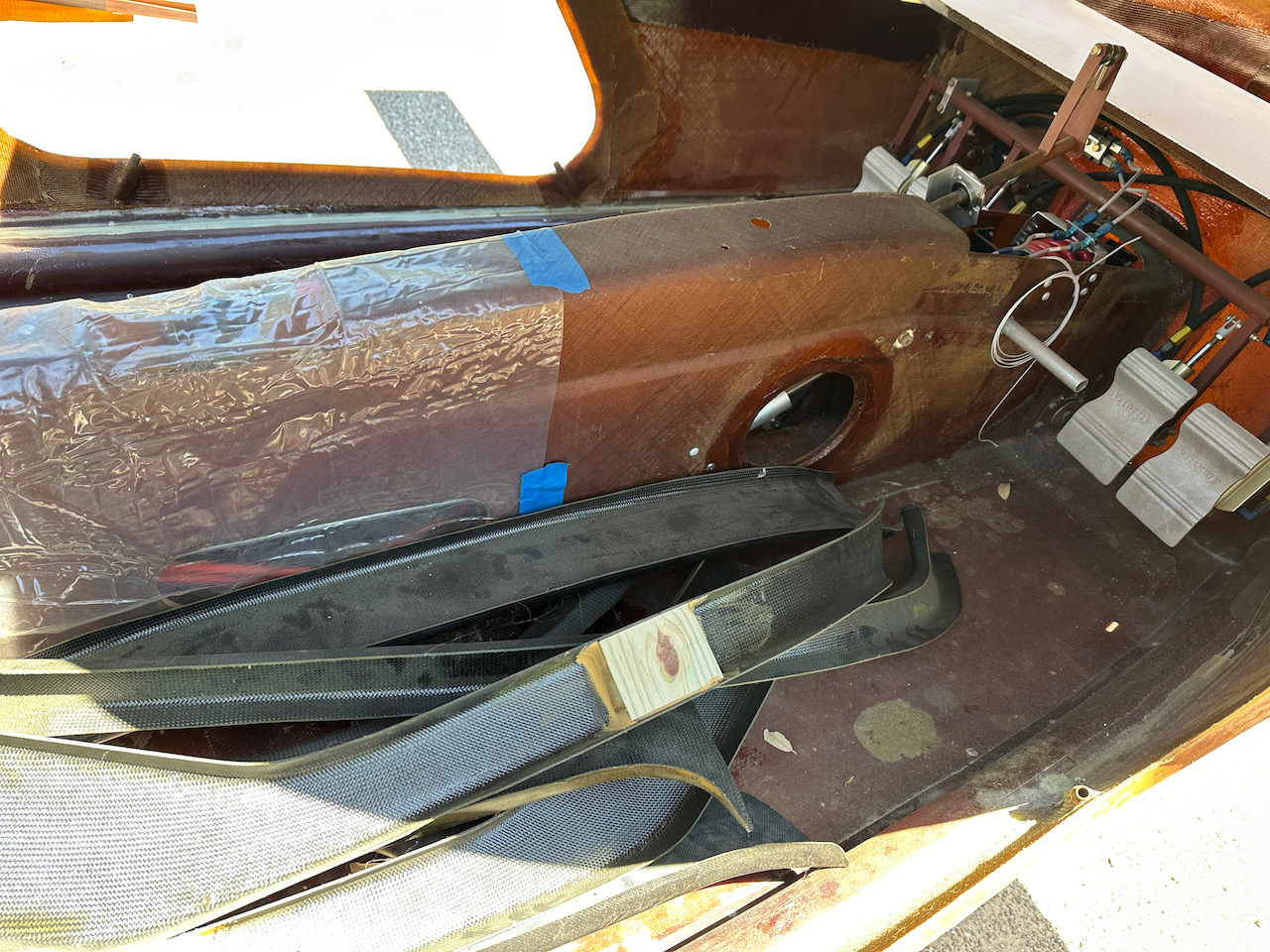
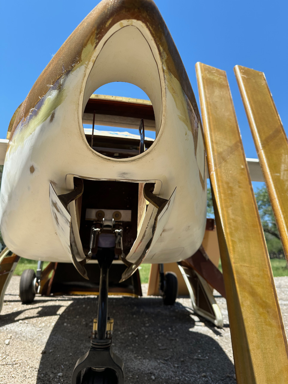
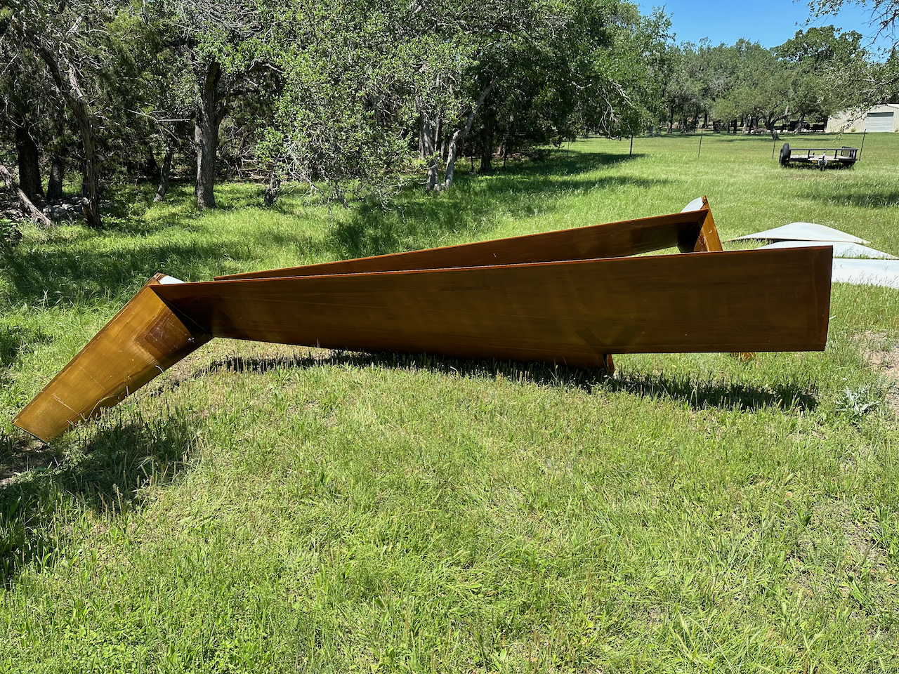
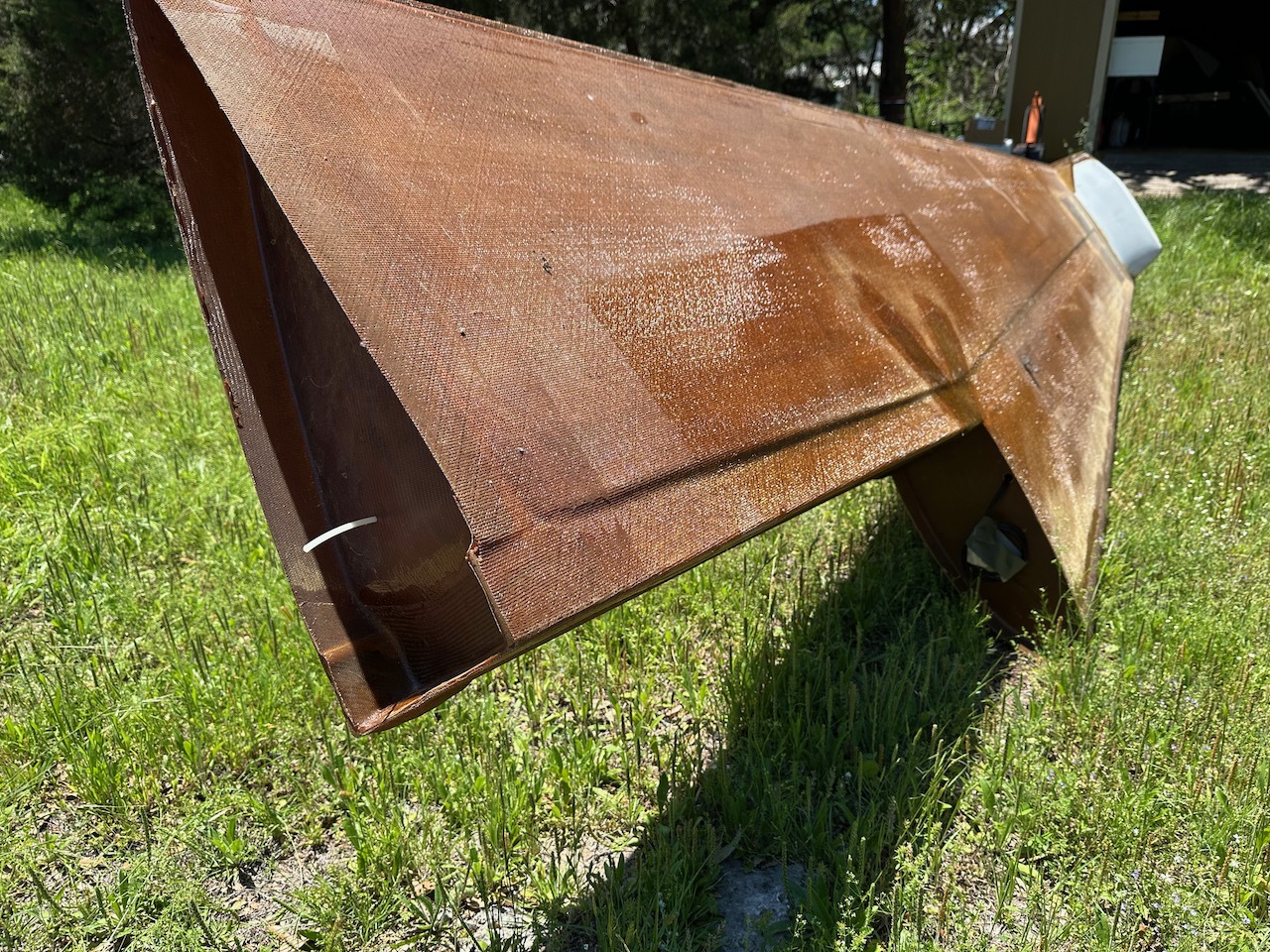
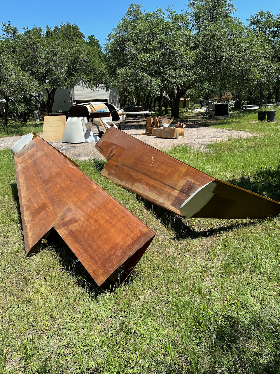
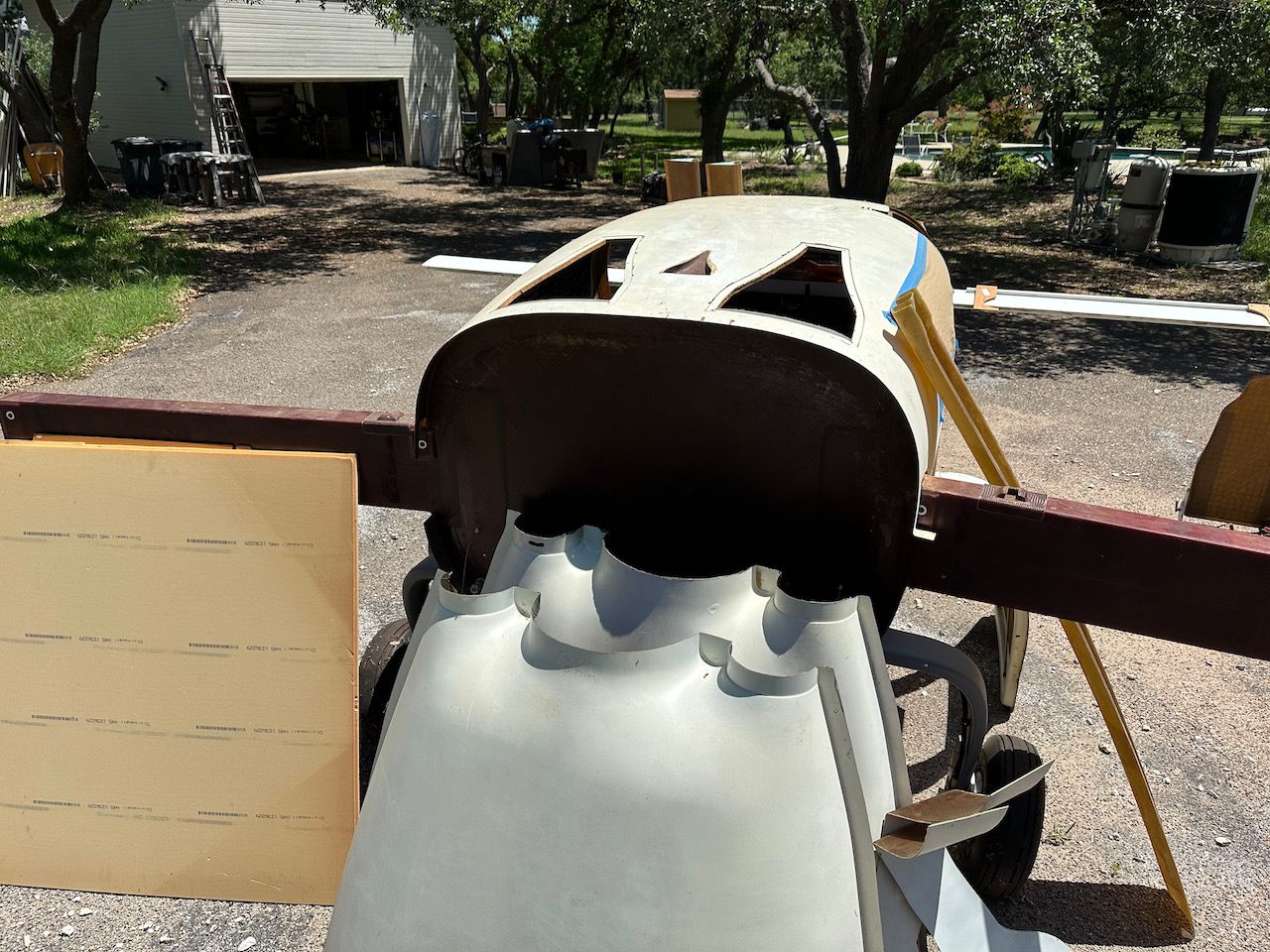
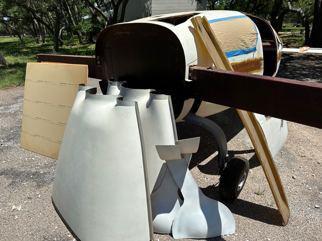
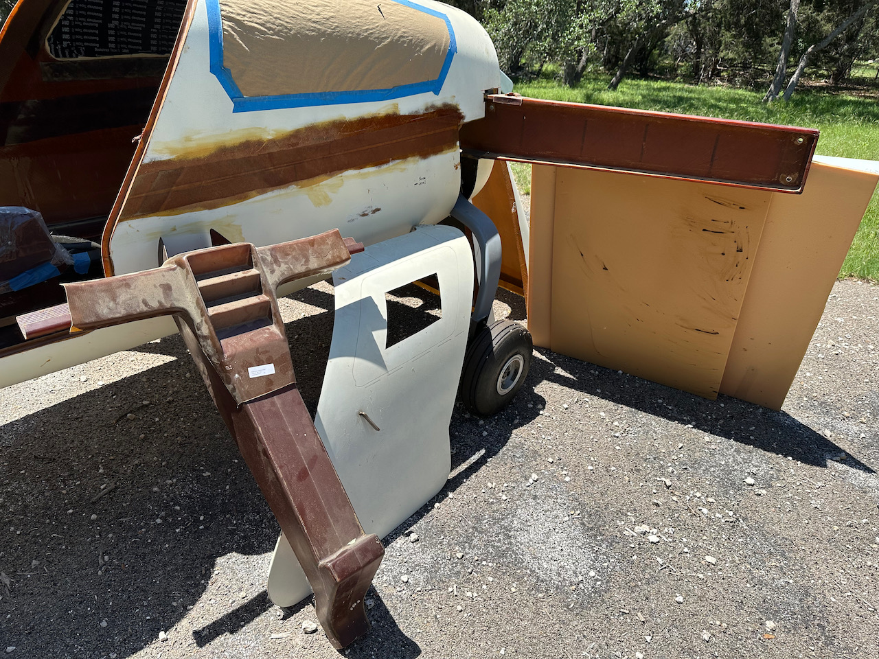
So the Velocity kit is for sale. Here are some pictures that I took of the fuselage and wings in their present state, along with photos of all the parts that go with them. I have heard that the factory has a many-month wait time for delivery of new kits. Purchasing this kit will let you start building NOW, with no wait, and also give you a head start on some of the assembly, all for a lower price than the factory list price!


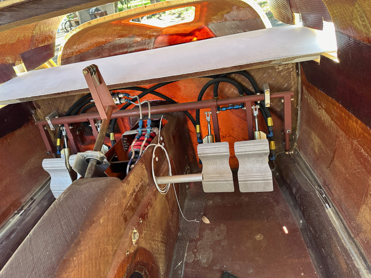


Door Pin Receptacles and Structural Beams
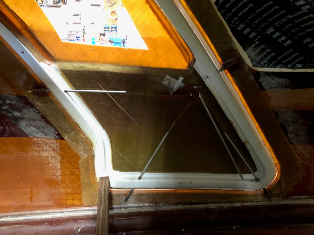
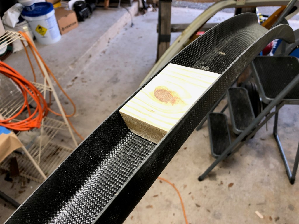
With the doors in place, the steel receptacle sleeves that will accept the door pins were positioned with wooden spacers, filleted in place with micro, and covered with BID.
The carbon fiber structural members that fit around the doors and across the ceiling were sanded to fit the inner surface of the fuselage. The seat belt hard points mounts were fabricated from wood shaped to fit inside the carbon beam.

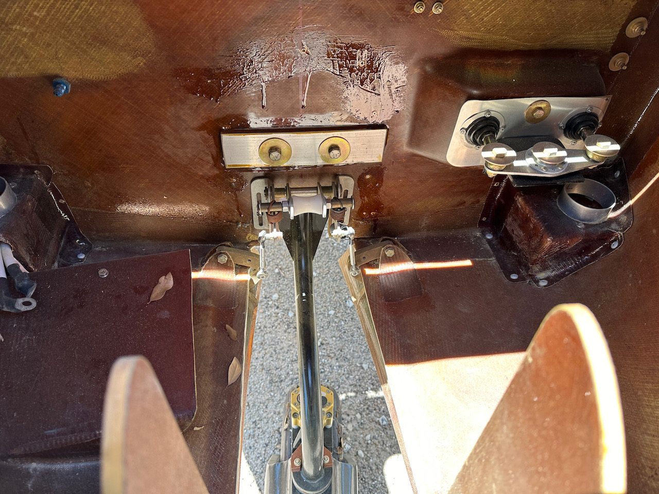
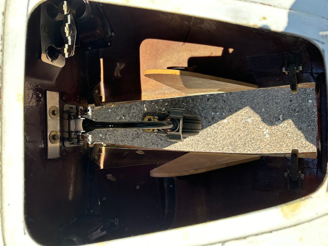
Door Hinge Attachment to Fuselage
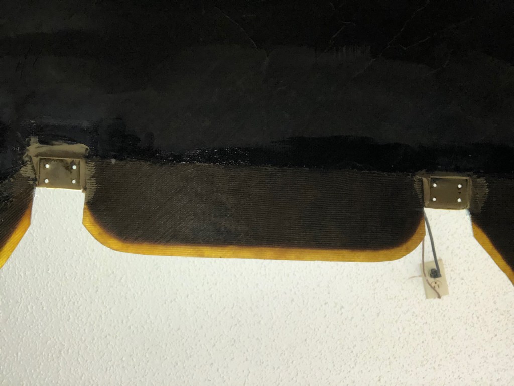
The pads on the inside of the fuselage were cut and shaped to accept the door hinges so that the doors fit reasonable well. Once in fit, the fuselage was match drilled, the hinges were tapped, and the top hinges were glued in place with a thin plastic tape release.


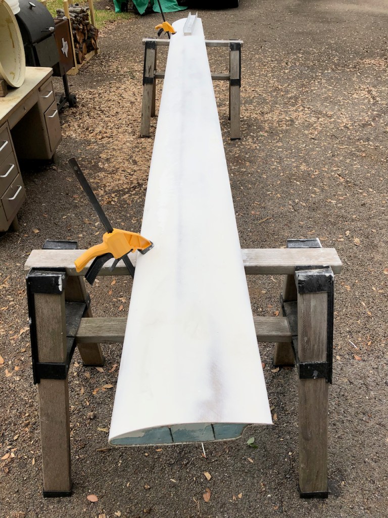
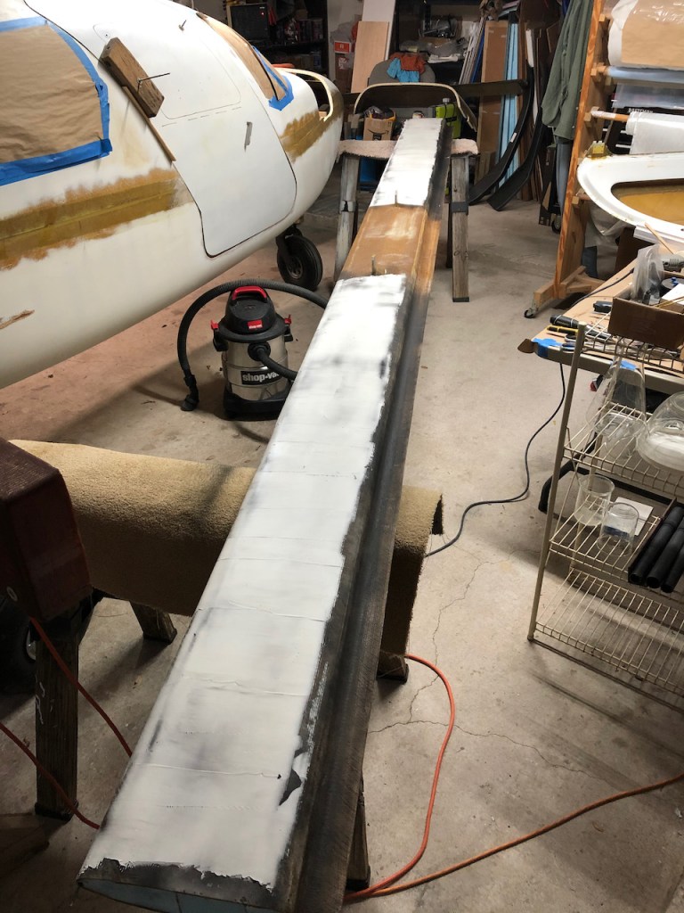
Canard Fairing, continued
Now for the top surface. Lots of micro, even more sanding.


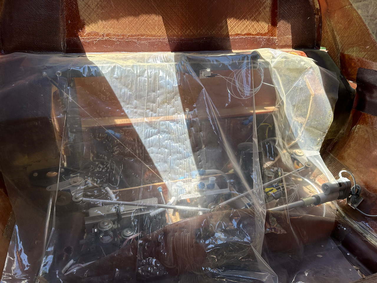
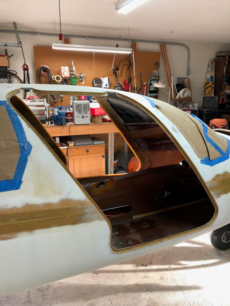
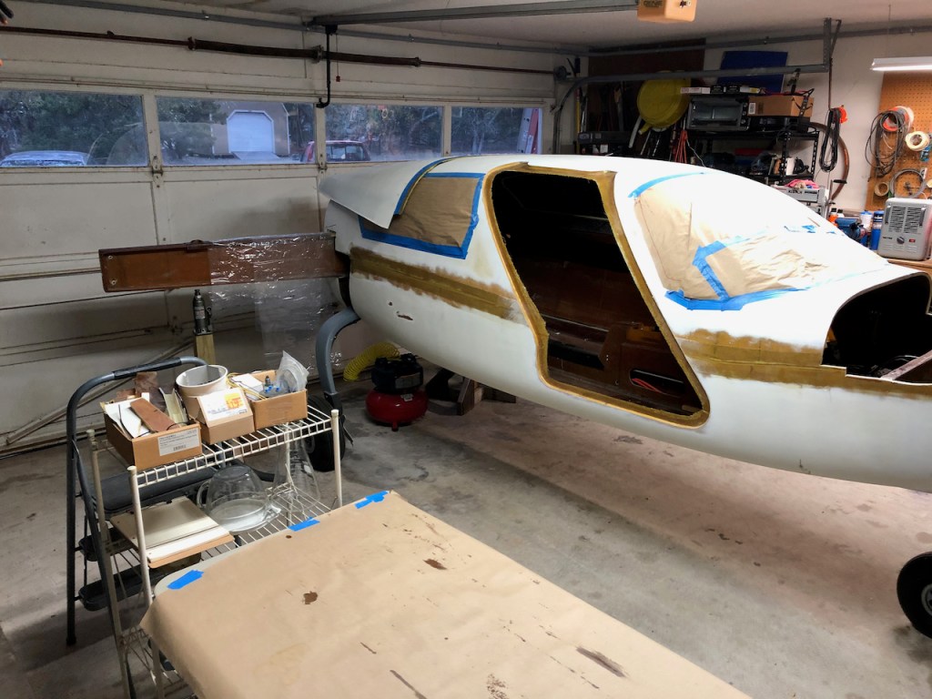
Making Airplane Noises
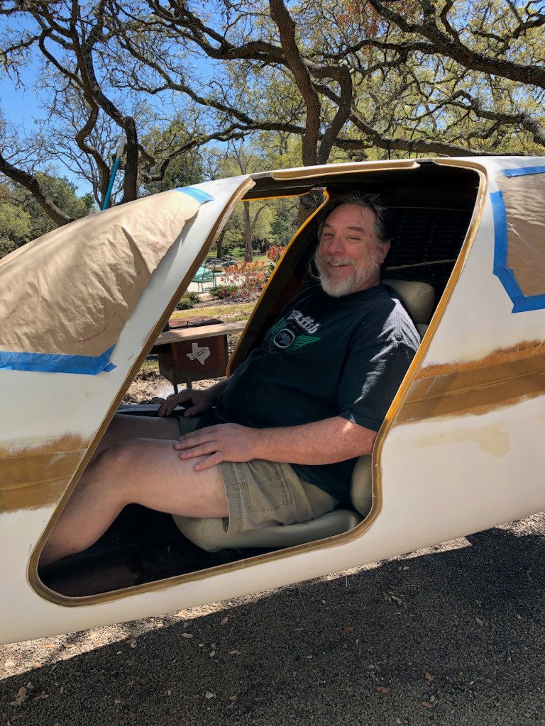
A beautiful spring day affords an opportunity to roll the airplane out of the garage, clean up, reorganize, put tools away where they belong. So why not sit in the plane and pretend that she is flying? It is a nice way to re-engage after the cold weather.
Even my co-pilot is excited!

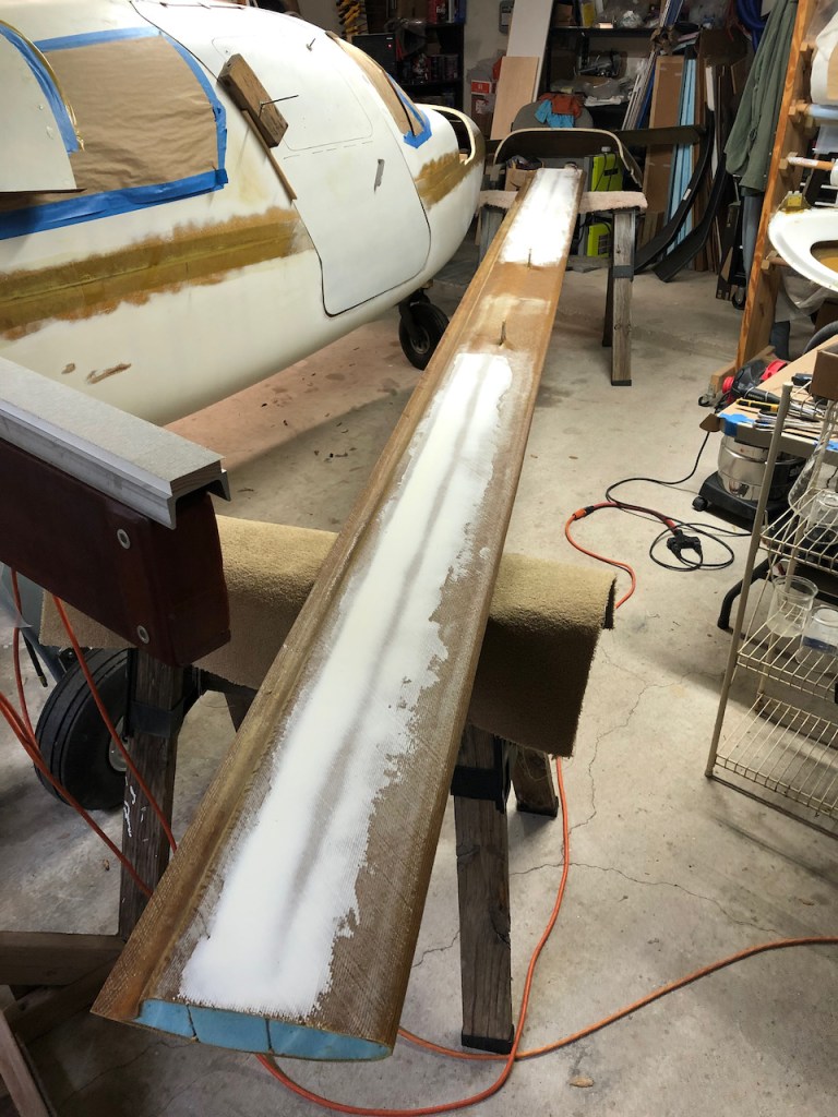
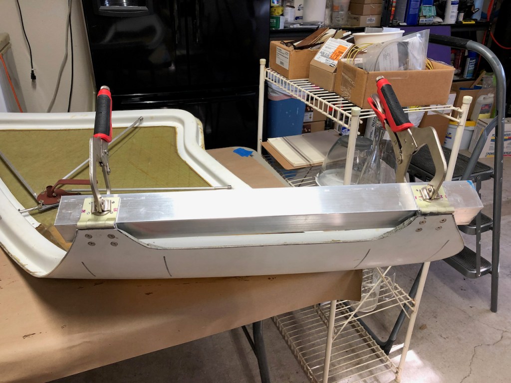
Canard Fill and Fairing
The canard low spots around the spar were first filled with micro and sanded flat. The the entire surface was covered with a thin layer of micro and was sanded flat using a long sanding board. This process will test your back and arms. And patience.


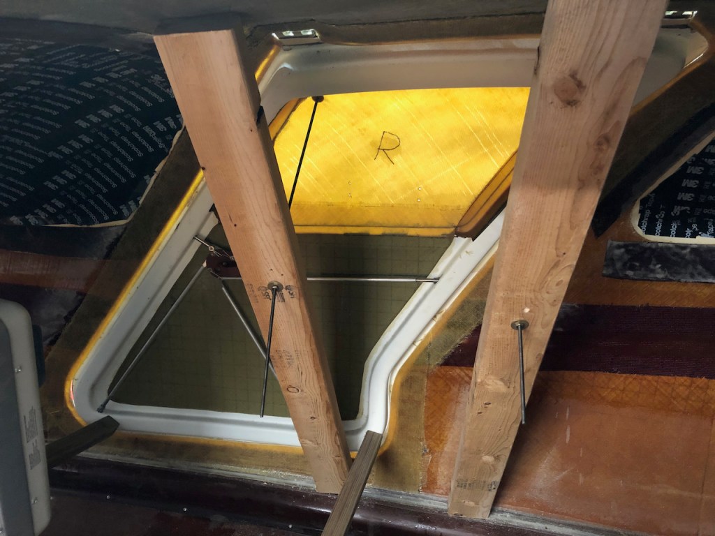
Fitting Doors
What a pain in the ass. The doors do not have the same shape as the fuselage, so they have to be “coaxed” into shape with force and heat, applied over a long period of time. I used all-thread rods to pull the doors in some places, and 1×1 dowels to push in other places, all while keeping the doors toasty hot with halogen lamps. Crude, and not very effective.


Door Hinges
The door flange was trimmed to a uniform size along the door perimeter.
The door hinges were constrained to be parallel with an aluminum angle, and were bonded to the door tabs. The tabs were drilled to match the hinges, and then the hinges were tapped. The door tabs were countersunk for the screws, and then the hinges were bonded with cabo, pulled flush with the screws, and covered with BID.


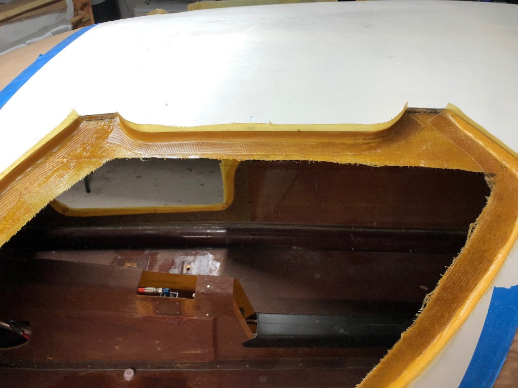
Door Seal and Flange
The foam was dug out from between the fuselage halves and filled with micro, followed by a 2xBID tape to fillet the door flange to the fuselage.

Cowling and Door Flanges
The cowling top half was cut at the proper distance from the firewall, with hot glue retainers added to keep it in place as the cut progressed. The inner surface next to the firewall was then protected with duct tape, and a wet tape was used to make a flange. After curing, the fuselage and flange were drilled for clecoes, the cowling was removed, and sanded to clean up.
The door cutouts were hot-glued back in place after covering their inside surfaces with duct tape. Layup tape was then used to create an inner door flange.


