Aileron Trim Actuator

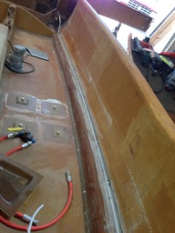
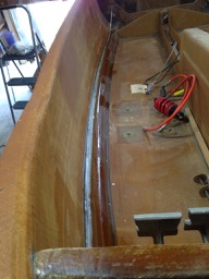
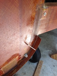
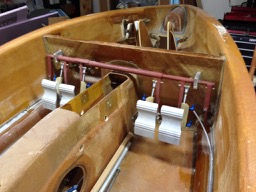
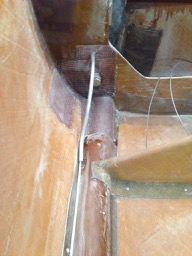
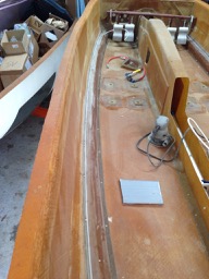
Replaced the cheesy gearmotor-and-string contraption for aileron trim that came with the kit for an upgraded electric trim actuator. The factory sells this upgrade, which is a modified commercial linear actuator with an integral spring. This is very similar to the mechanism that Vance Atkinson devised and built for his Long-EZ. Very nice. It comes with a rod end that easily attaches to the aileron torque tube bell crank. Hard point installation is straightforward in the fuselage just aft of the whale tail and above the conduit.

Aileron Torque Tube Bearings

While positioning and repositioning the aileron torque tube in the keel, I started thinking about how one might perform maintenance. I was also not happy with the way the build manual suggested to hold the torque tube bearings into their mounting angles.

I designed a very simple retainer ring that holds the bearing very nicely into the mounting bracket. I also modified the bracket by cutting out a portion of the bracket so that the torque tube can be removed simply by removing the three socket screws that retain the bearing, and then slipping the bearing out of the mounting bracket. Finally, installing nut plates on the mounting brackets makes their installation into the keel easier.

Aileron Trim Actuator

The factory upgraded the aileron trim mechanism around the same time that they moved to the pushrod-bellcrank mechanism. The end plate at the “whale tail” that holds the aft end of the aileron torque tube was made smaller, and the old trim motor, string, and spring were eliminated. The replacement is a linear actuator with an integral spring.

There are no instructions from the factory for installation, so I plan to install the actuator on the pilots side.

Drilling Aileron Torque Tube

The aileron torque tube sections, the universal joint, and the rear torque tube bell crank have to be drilled so that the sections and parts will mate together tightly and in proper alignment. I used the wing spar and firewall as a table and clamp plate, respectively, to hold the assembled torque tube in position for drilling the last hole through the torque tube bell crank. The torque tube bell crank and the forward side-stick bell crank have to both be aligned vertically when attached. Its a kluge, but it worked OK. The holes were drilled slightly undersized, and then reamed for an interference fit for the AN-3 bolt. Slop is unacceptable.

Aileron Bell Crank Supports

The factory is replacing the push-pull cable aileron linkage with a new pushrod linkage. There are now bell cranks mounted on the landing gear bulkhead that connect directly to the control torque tube that passes through the keel tunnel.  These bell cranks transfer motion to two long pushrods that pass through the MLG bulkhead and the firewall, connecting directly to the aileron control surface torque tubes in the engine compartment at the trailing edge of the wings.

The mating surface on the MLG bulkhead had to be filled and leveled to make a good mounting surface for the bell crank mounting bracket.  Then holes were drilled through the bulkhead for the pushrods.  I now have to figure out some way to determine the position of the corresponding hole in the firewall bulkhead….

Rudder Cable Conduits

The rudder cables travel to the rear of the aircraft in Nylaflow tubing that is attached to the top of the cable conduits in the floor of the fuselage.  The Nylaflow is held in place with 1x bid, so I used this opportunity to use my new roll of 2″ wide bid tape, just wetting it with Velocipoxy as I worked down the length of the fuselage (both sides).

At the landing gear bulkhead, the Nylaflow tubing passes through a section of aluminum tubing that passes just outboard of the MLG leg and then through the firewall.

Center wing spar and landing gear

Leveling and centering checked again, and then the center wing spar was glued into place with structural adhesive+flox+cabo and clamped. MLG legs were bolted into place and bushings glued on both ends. MLG were then removed again. Thick tapered layups of triax were applied to link MLG bulkhead, firewall, and center spar together.

Aft keel was cut down for -5 option, and carbon keel cap was placed in position (not glued). NLG linkage, shock absorber, and over center link was installed in keel. NLG swing check completed.  NLG bushings and over-center hard points were mounted inset in keel skin, so careful cutting of outer skin and foam was needed.

Rudder pedals were positioned and attached to canard bulkhead and linkage was attached to see-saw.

Topside layups joining winglets to wings applied and curing. Strap layups at spar bolts applied – wings and winglets are completed (for now)!!!

IMG_3492

Ducting, bulkhead work, and controls

NACA oil scoop was reinforced with 2-ply BID top and bottom of scoop. Additional strengtheners glassed to area of gear bulkhead around the gear pulley openings.

Rudder cable see-saw installed on canard bulkhead, and battery shelf positioned and clecoed in place. NLG actuator bolted into place on fuselage centerline.

Heat duct (pre-fab part) sawed in half and internal flange fabricated by using waxed Al tape on one half and bonding 2-ply BID across seam.

Iteratively cut lower cowling along cut line aft of firewall, holding it in place with hot glue and wooden sticks.  Added a 2-ply BID layup to strengthen joint between firewall and fuselage in region of cowl flange.

IMG_3458

Saturday work

Wings were put back on wing fixtures for fitting of winglets.  Wing and winglet contours adjusted by sanding until the edges were within 1/8″along the join line. Foam was partially cut out of spar and both LE and TE blocks to accept the inner layups. BID layups placed on inner seam, and then dug-out foam was replaced with micro.  A block of foam was then glued in place with micro, and after cure, was contoured with knife and sanding to blend lower wing and outer winglet surfaces.

NACA oil cooler scoop was cleaned up, with excess cabo ground away and outside lip of scoop sanded flush with fuselage skin.

MLG cable pulley holes were cut in gear bulkhead. Strips of 2-ply BID layups were placed along gear bulkhead and canard bulkhead for strengthening.

Rudder pedal and toe brake assembly was built up from parts.