Hydraulic Pump Modifications

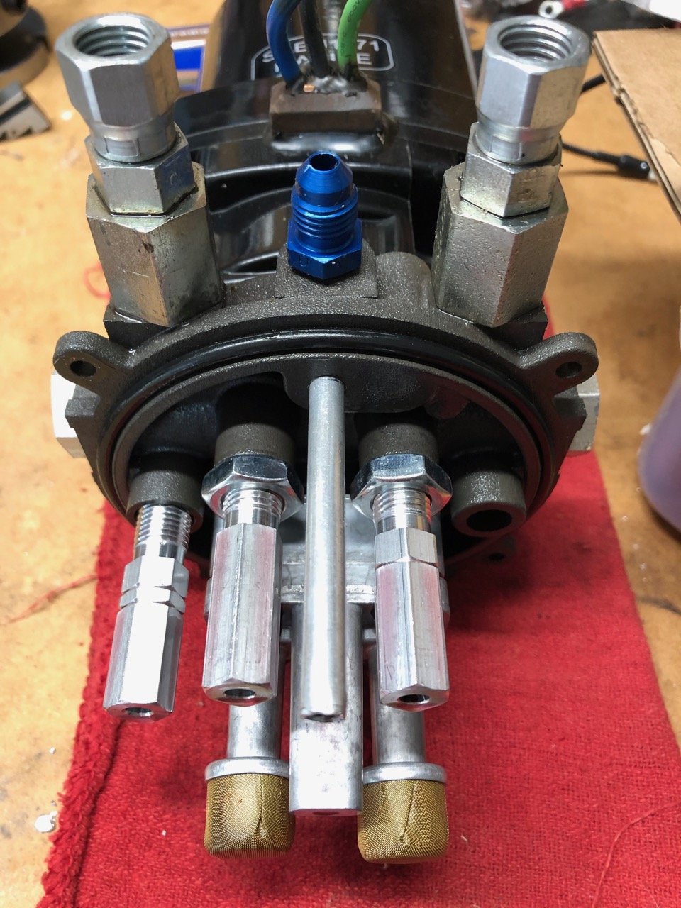
It turns out that the version of hydraulic pump supplied to Velocity is configured with the UP side as the high pressure side and the DN side as the low pressure side. The pump itself is symmetrical, producing full pressure independent of rotation direction. Changing the DN side to be the high pressure side requires swapping the internal pressure relief valves at the base of the pump, and recalibrating them for the desired pressure.

As an aside, simply switching the hydraulic lines between the UP and DN side will not work, because the internal valve configuration of the pump requires that hydraulic cylinder retraction (which is our gear up) occurs on the DN side of the pump. The difference lies in the excess hydraulic fluid volume that must be supplied to the cylinders when the UP side of the pump runs (our gear down). Confusing? You betcha.

Scott S. offered to do this PRV swap and calibration at the factory, but I had the required equipment to do it and adjust the PRV settings.

First Landing Gear Swing Test

The nose and main landing gear hydraulic systems were connected to the hydraulic pump and power was supplied to the hydraulic pump bus. The emergency gear operation switch (in the pilot’s emergency panel) was wired up to allow testing of the gear retraction and extension.

As the video shows, the hydraulic pump pressure relief valve opens before the high pressure set point on the solenoid switch is reached. The result is that the hydraulic pump continues to run after the gear is up, and the “screeching” noise is the pump’s DN-side PRV opening.

Further investigation is required.

Nose Landing Gear Door Modifications

A few modifications were made to the nose landing gear doors and their open/close linkage.

During landing gear extend/retract testing it was difficult to find a nose gear door adjustment that satisfactorily held the doors shut, but opened promptly enough to prevent the doors from rubbing the tire on extension. I decided to remove the raised foam area on the doors to help prevent interference with the nose tire. The foam was sculpted and formed with EZ-poxy with flow, and then covered with carbon fiber for extra strength.

The rod ends on the nose gear door closing linkage were replaced with more sturdy and larger -3 versions that will not pop apart. I used left-threaded rod ends on the doors, and tapped an aluminum rod to act as a pushrod whose length can be adjusted by twisting it like a turnbuckle.

MLG Cable Attach

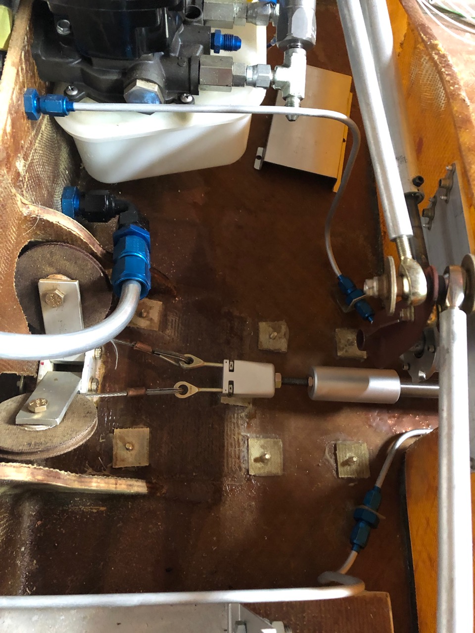
Because space in the keel is at a premium, I designed a smaller gizmo that attaches the MLG cables to the hydraulic cylinder. Fabrication of these parts are beyond the scope of the tools I have in my shop, so I set this out for fabrication – ouch$.

The new device has several features. It has an aluminum cylinder that fits over the actuator shaft, but it is threaded on a 1/4″-28 rod and so the MLG retraction limit can be adjusted by simply screwing the cylinder to the desired location and then locking it in place with a jam nut. In addition, the MLG cable rod ends fit into the device and tension/travel can be independently adjusted with nuts. Once adjusted, the nuts are secured with safety wire.