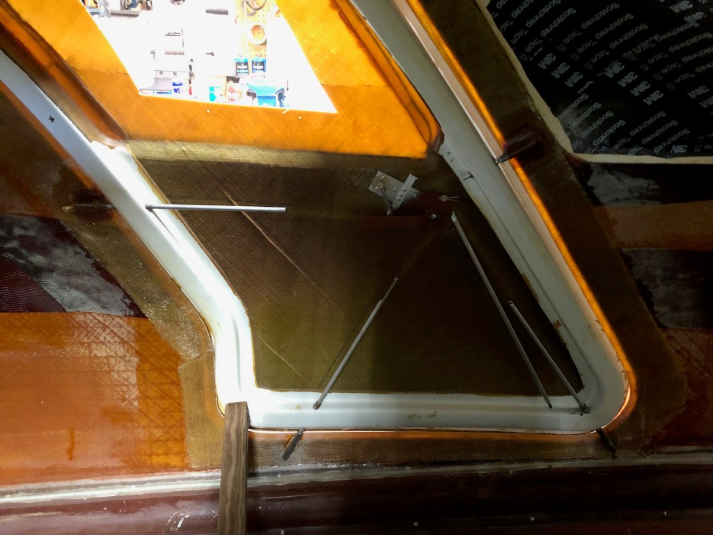
With the doors in place, the steel receptacle sleeves that will accept the door pins were positioned with wooden spacers, filleted in place with micro, and covered with BID.
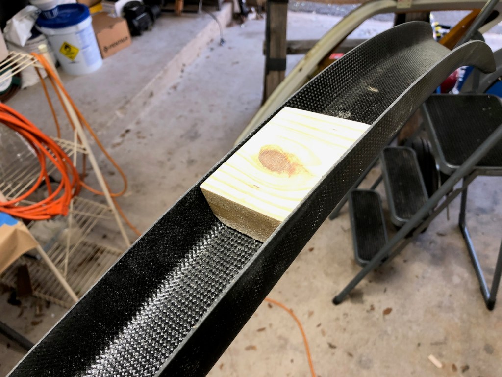
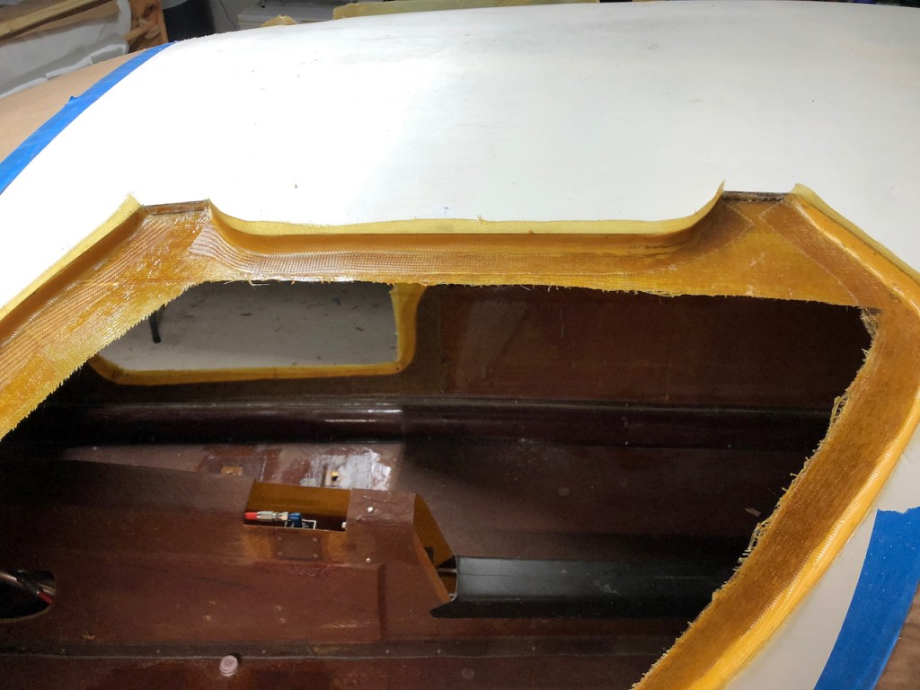
The carbon fiber structural members that fit around the doors and across the ceiling were sanded to fit the inner surface of the fuselage. The seat belt hard points mounts were fabricated from wood shaped to fit inside the carbon beam.