Nose Landing Gear Hydraulics

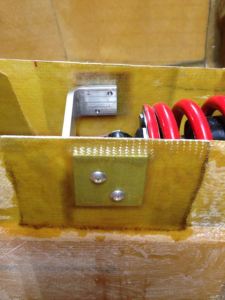
I have made the decision to mount the hydraulic pump in the rear of the aircraft, which means that hydraulic lines will need to go no farther forward than the nose landing gear retraction assembly.  This prevents any hydraulic lines from having to traverse the over-center mechanism and eliminates the tight mechanical fit at the canard bulkhead.  Hydraulic lines were made and attached to the nose gear actuator and the dump valve, and the dump valve was mounted to its recess plate.

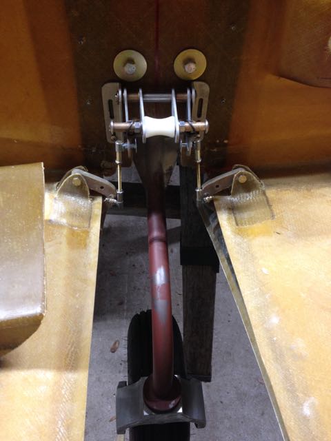
The nose landing gear door retraction assembly was installed and adjusted for the desired landing gear limits.  I sure don’t like the way the rod ends attach to the door hinges – this is going to have to change.  I also converted to using all-thread for the pull struts instead of the solid standoffs in the kit.  I will trim the standoffs to the proper length when I am finally happy with the door closing adjustments.  I still need to make the nose gear fork guides.  I have noticed that it is easy for the gear to bind either on the doors or in the opening if it is not exactly straight.  Waiting on some 1/4″ divinycell to make the guides.

img_3750

Nose Landing Gear Adjustments

Numerous adjustments were made to the nose landing gear retraction assembly, mainly because I was not happy with some clearances and travel limits of various parts.  First, the rear surface of the over-center gas spring was rubbing on the sharp corner of the linkage bushing retainer plate.  Easily fixed by grinding off the corners of the retainer plate.  Next, the nose gear actuator cylinder was binding on its mounting brackets at about half-travel, putting undue torque on the bottom of the fuselage.  The actuator assembly was removed from the interior of the keel, the brackets were trimmed to eliminate the interference, and the unit was replaced.  Not easy to get to….

The lower hard point for mounting the gas spring was placed where the manual specified, but in this location the shock strut contacts the bottom of the gas spring when the nose landing gear is retracted.  I decided to move the bottom gas strut mounting post aft by one inch.  This necessitated extending the plywood hard point aft.  The old hard point was cut in half and the aft half removed, and then a new plywood hard point was glued in with structural epoxy, filleted with cabo, and then covered with 2x BID.  After this cured, the new hole and countersink for the gas strut post was drilled and the gas strut was installed. There was very little change in the over-center pressure (it was actually increased) after this modification, and now the nose landing gear can retract without mechanical interference all the way to the limits of the actuator cylinder.

I also beefed up the nose landing gear over-center bracket  attach points with 2″ aluminum hard points glassed in to the keel side wall.  Just in case the actuator travel limits get out of adjustment, it will be harder for the hydraulic system to damage this part of the keel.  Its only thin fiberglass, and looks like it needs reinforcing anyway.

img_3749