Drilling Aileron Torque Tube

The aileron torque tube sections, the universal joint, and the rear torque tube bell crank have to be drilled so that the sections and parts will mate together tightly and in proper alignment. I used the wing spar and firewall as a table and clamp plate, respectively, to hold the assembled torque tube in position for drilling the last hole through the torque tube bell crank. The torque tube bell crank and the forward side-stick bell crank have to both be aligned vertically when attached. Its a kluge, but it worked OK. The holes were drilled slightly undersized, and then reamed for an interference fit for the AN-3 bolt. Slop is unacceptable.

Landing Gear Dump Valve

I decided to put the landing gear hydraulic dump valve inside the keel, where it will be accessed by opening a door just under the pilot’s right elbow. I plan to also put the main fuel shutoff knob here. This location is above the aileron torque tube, and should not interfere with other stuff in the keel.

An aluminum bracket was made to hold the valve itself, and a drilled aluminum backing plate was glassed onto the exterior wall of the keel to be a hard point for the valve.

Landing Gear Retraction Test

With the main landing gear filled and primed, and with the brake lines attached to the gear legs, I did a retraction test to make sure that there was still no interference with the MLG cutouts in the fuselage (which had to be widened slightly), and the aluminum tubing for the header tank vent and drain. The trusty nitrogen cylinder was used to do the retraction, and all was successful.

Brake Lines and Brake Calipers

The routing of the brake lines needs to be such that there is adequate length to accommodate the retraction of the gear, and that the excess stays out of the way of the gear leg during the MLG movement into the down position.  The flexible brake hose was routed close to the gear leg pivot axle, and from there, terminates at an AN bulkhead elbow fitting through the landing gear bulkhead.  Hard aluminum tubing will run to the front of the aircraft from these fittings.

A significant portion of the landing gear door holder plate had to be removed to prevent interference with the brake caliper.  I want to be able to remove the brake caliper without having to remove the gear axle, so this was a necessity.  I will find alternate ways to hold the gear doors when that time comes.  Finally, a 3/8″ thick brass bushing was used during assembly of the MLG over-center mechanism to hold the mechanism forward and prevent interference with the header tank fittings.

Fill and Finish MLG Legs

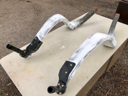
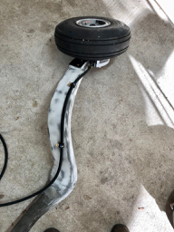
The next step on the MLG legs is to fill the surface, smooth, and get a coat of primer onto the surface.  I have deviated from the plans and I am using steel-braid brake line and AN hydraulic fittings for the brakes instead of the Nylaflow tubing.  I added four studs to the lower surface of the gear leg to attach Adel clamps to hold the brake line in place.  The studs consist of a MS24694 #8 x 1/2″ screw that is placed through the center of a thin 1″ square wafer of phenolic (or fiberglass). The wafer and screw are adhered to the surface with a dollop of thick cabo, and the squeeze-out is used to make a smooth fillet around the wafer. This is then covered with 2x bid. When cured, the edges are sanded smooth.

The coarse weave of the carbon fiber and fiberglass socks on the gear legs were filled with Velocipoxy+micro, and contoured with a spatula.  After this cured, the legs were sanded smooth and excess micro was removed. Then, cabo was added to Velocipoxy until a syrupy consistency was obtained.  This mixture was spread on the surface of the sanded micro  with a squeegee to fill pinholes.

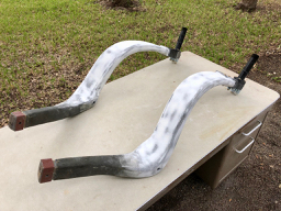
The pinhole fill layer was then sanded again to eliminate any ridges left by the squeegeeing.  After masking the booties and the upper portions of the gear leg (where they fit in the socket), two coats of UV Smooth Prime were brushed onto the gear legs. These coats were sanded smooth with 320 grit paper – this is easy since the UV Smooth Prime is so soft.

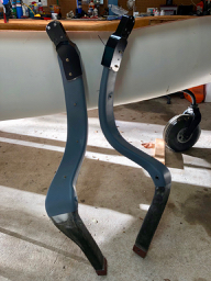
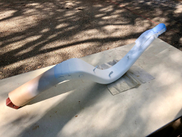
Once the UV Smooth Prime coats (which fill all remaining pinholes) are sanded baby-skin smooth, the gear legs were sprayed with 3 cross-coats of Stewart Systems Eko-Prime, which is a water-borne gray primer.  Eko-Prime is harder than the underlying UV Smooth Prime, and should be hard enough to fly with.

Fitting Booties on MLG Legs

I purchased the aluminum “booties” from the factory, as this is an opportune time to install them.  The booties are supposed to help with dissipation and spreading of the thermal load due to braking during the landing rollout.  Some folks have experienced sag of their landing gear legs due to the temperature rise in the brakes during extended taxi and hard braking.

My first job was to remove the existing axle from the gear leg.  This was impossible to accomplish without a hydraulic press.  Once the axles were removed, the cut line on the bottom of the gear leg was marked to fit the inside shape and angle of the bootie, while replicating the position of the axle flange.  The gear legs were (gulp) cut with a jigsaw – no turning back now…  Then the edges and corners of the gear leg were sculpted to fit the interior shape of the bootie socket.

After reinstalling the gear legs into the fuselage and verifying that the height and angles of the axles were correct, the gear legs were glued into the booties with Velocipoxy + cabo, with a smooth fillet around the edges of the joint.  After curing, the holes were drilled for the bootie through-bolts.

Aileron Bell Crank Supports

The factory is replacing the push-pull cable aileron linkage with a new pushrod linkage. There are now bell cranks mounted on the landing gear bulkhead that connect directly to the control torque tube that passes through the keel tunnel.  These bell cranks transfer motion to two long pushrods that pass through the MLG bulkhead and the firewall, connecting directly to the aileron control surface torque tubes in the engine compartment at the trailing edge of the wings.

The mating surface on the MLG bulkhead had to be filled and leveled to make a good mounting surface for the bell crank mounting bracket.  Then holes were drilled through the bulkhead for the pushrods.  I now have to figure out some way to determine the position of the corresponding hole in the firewall bulkhead….

Powder Coating NLG Parts

In an effort to make a few things look spiffy, I sent a bunch of metal parts to a local shop to be powder-coated.  Most of these parts were for the NLG actuating mechanism, the NLG fork, and the NLG shimmy dampener.  I also got the aileron bell crank brackets and the MLG leg booties powder coated.  My aircraft is going to have black legs – sexy.

SCAT Hose Flanges

I refuse to buy a bunch of the expensive metal flanges for the attachment of SCAT/SCEET hose for heating and cooling.  So I bought one each of the two most probable sizes if hose I will be using, and used them as a template to make a mold so that I could replicate them in fiberglass.  Mold release wax was used liberally on the metal, and then a liberal layer of cabo on the surface (poor mans gel-coat) followed by 4x bid was laid up on the outside of the metal template to make the mold.  I added graphite to the epoxy to make the mold black.  After smoothing and filling and waxing, I could punch out replicas of the SCAT hose flanges.  I will use these on the various air boxes and ducts for the cabin heating and cooling system.