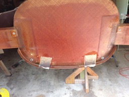
I think I have decided to use a Continental IO-550 engine. The engine mount bolts for the TCM engines come through the firewall in the lower corners, and the standard header tank interferes with that location. So I have to modify my beautiful header tank by cutting the corners off.
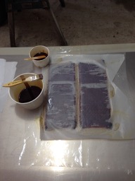
The cut line was marked, and the oscillating tool made short work of the cuts. Two thick lay ups (8x bid) were used to make the new corner walls. These were coated, sanded, and coated with EZ-poxy to form a fuel-tight inside wall, then were bonded to the header tank with a fillet of cabo and 2x bid around the perimeter. New mounting ears were also added.
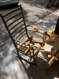
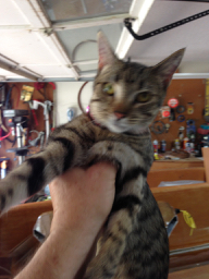
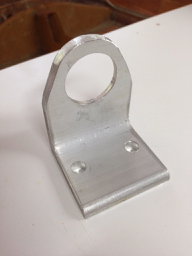
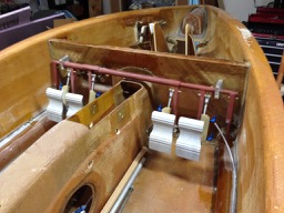
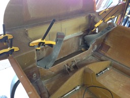
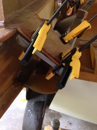
Taking care of some miscellaneous items associated with the main landing gear. First things first, re-glue and clamp my favorite rocking chair using resorcinol-phenol glue – amazing stuff. Ripple the hangar cat approves. I plan to mount the MLG dump valve inside the keel, accessible by a fold-up door at the pilot’s right armrest, instead of in the inset cutout in the side of the keel. So I made some sheet metal bracketry to attach the dump valve to the inside of the keel wall. Also, the MLG retraction pulley mount was beefed up with a fillet of cabo+flox, followed by a layer of triax. I also ground off the shoulders of the MLG hydraulic cylinder mounting bracket because this was in the way of the hydraulic fittings. Now the hydraulic lines can be installed fore/aft without making sharp bends inside the keel.
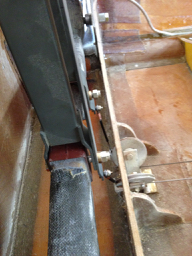
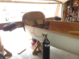
I finally received the main landing gear hydraulic cylinder from the factory, over a year late. It was installed in the keel tunnel and the retraction cables were attached to the MLG over-center mechanism. Instead of hooking up the hydraulic pump, I decided to use nitrogen to test the retraction. There is a stored energy problem with using gas, so I was very careful to manually help the retraction through the portions that required the most pressure. I found that the over-center lock bar disengaged at about 380 psi, but it only required about 100 psi to hold the MLG in the retracted (up) position.
There are always things that slow you down, make you scratch your head, or make you shake your head in wonder.
As part of my kit, the factory included some parts that were not labeled, I could not find in the manual, and had no clue what they were. I sent some pictures to Scott S. and he identified them as aileron bell cranks for the V-Twin….. It turns out the V-Twin and the newer XL-RG kits are not using the push-pull cables from the whale tail to the ailerons. They are replaced with solid push rods and bell cranks, and these parts are part of that new system (completely undocumented). Scott quickly got the correct parts to me, as well as a new Atkinson-type aileron trim actuator/spring mechanism to replace the previous cheesy string-belt trim system.
I ordered several 6 foot lengths of 5052-O aluminum tubing from Aircraft Spruce to use for brake lines. The package got mistakenly routed to San Antonio instead of Austin, and it was a few days late arriving at the house. From previous experience, I know that Aircraft Spruce is pretty good about shipping long lengths of tubing taped or affixed to a piece of wood to keep them straight. Never mind that – when my package arrived, all of the tubing was folded in half and stuffed back into half the box, which was now only 3 feet long. The wood stiffener was missing. I can only guess that somehow the box was too long for the guys in San Antonio, so they just shortened it….. I sent the great folks at Aircraft Spruce a photo and they happily sent me another order of tubing.
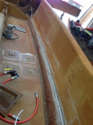
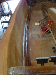
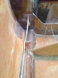
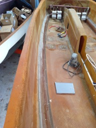
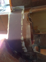
The rudder cables travel to the rear of the aircraft in Nylaflow tubing that is attached to the top of the cable conduits in the floor of the fuselage. The Nylaflow is held in place with 1x bid, so I used this opportunity to use my new roll of 2″ wide bid tape, just wetting it with Velocipoxy as I worked down the length of the fuselage (both sides).
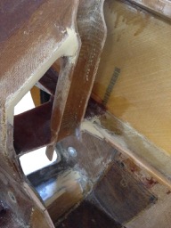
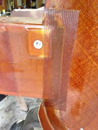
At the landing gear bulkhead, the Nylaflow tubing passes through a section of aluminum tubing that passes just outboard of the MLG leg and then through the firewall.
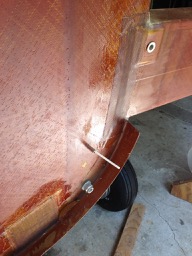
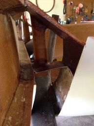
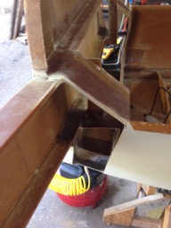
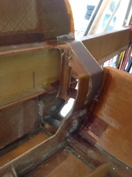
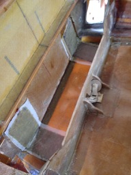
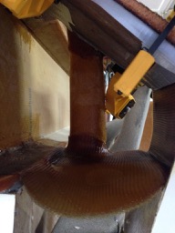
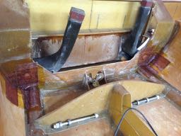
The manual calls for beefing up the area where the landing gear bulkhead is connected to the main spar, which is also the area where the MLG leg sockets are. I had already put the foam and 2x bid on the trapezoidal connection between the landing gear bulkhead and the spar, but it needed a layer of glass underneath (tricky clamping) and another strengthening layer on top.
Thick 3x triax layups were placed in the area where the engine mount bolts will pass through the firewall – on both sides of the firewall. I guess I have decided to use a TCM IO-550 engine. The upper triax straps will have to wait until the top is bonded on. Its tedious, but good technique requires removing ~1/4″ of foam from sandwich panels, and then filling it with micro and sanding it smooth after it cures. Some of these joints and tight areas have to be sanded by hand because there is not room for a sander…
Some stiffening layups need to be added to the landing gear bulkhead in the region of the MLG pivot bolts, and in the transition area between the main spar and the firewall. Did a nice fill with epoxy+cabo, plus some flox around the spar area, then some layers of triax around the MLG bolts and bid at the main spar. Added peel ply to keep it neat.
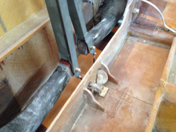
Received the new shimmy dampener from the Velocity factory. Scott S. asked that I send the big aluminum NLG fork to the factory so he could drill the mounting holes. Scott turned it around in a little bit over a week, and then my job was to drill the flange at the end of the gear leg to accept the bolts for the pivot pin holder. Getting up close to the gear leg with a drill is difficult, so I opted for an extra-long bit so I could keep the alignment of the drill bit to the normal surface of the flange. Also, some of the flange weld had to be ground away so the pivot pin holder would lie flat on the flange. Test fit and assembled – seems to work great.
I purchased a squirrel-cage blower to use to recirculate air in the cabin, and as a side experiment, I wanted to measure the airflow characteristics of the fan. I tend to geek out on the physics aspects of things, so I set out to measure the zero-flow pressure and the no-back-pressure flow rate, and several intermediate points in-between. In analogy, its like measuring the source characteristics of a power source, where one would measure the open circuit (zero current) voltage, and the no voltage (short circuit) current, and points in between to get the source impedance.
So I rigged up a flow tube with several fixed-sized circular orifices, with dynamic pressure measured on both sides of the orifice to obtain (via the equations for compressible orifice flow) the air flow rate, and then an independent pressure measurement (re: atmosphere) at the fan output.
Measurements indicate (see graph below), that at a fan voltage of 13.5V, the measured airflow vs. back pressure (dots) agrees in shape, and is consistently above the manufacturer’s data (solid curve), which was taken with a fan voltage of 12.0V.
I think if I keep the resistance to flow low enough, this fan will deliver an adequate air flow. Further experiments will include measurement of flow resistance of SCAT and SCEET tubing.
I decided to install thrust bearings on both sides of the MLG pivot bushing to prevent the metal-metal (bushing to bolt-holder) contact and potential wear and slop in the MLG system. This mod was first described by Dale Alexander in the Builder’s Forum section of Velocity Views 1Q 2004. To accommodate the width of the thrust bearing, I had to grind down the existing steel pivots that have already been glued into the gear legs. Care was taken to grind only enough to fit the bearing in place, and to maintain the position of the gear leg on the pivot bolt (because the retraction mechanism has already been fit). The grinding was followed by fine filing to make sure that the remaining bushing edge was flat and perpendicular to the pivot axis.
After the thrust bearings were installed, the MLG legs moved very smoothly. The side of the fuselage and portions of the gear pockets were trimmed to allow the gear legs to retract fully without interference. Adequate clearance between the gear user legs and the sump tank fittings was verified.