Repaired Nose Gear Hydraulic Actuator

After repairing the seals, glands, and O-rings in the nose gear hydraulic actuator, I hooked it up to the nitrogen bottle and tested for leaks in both travel directions.  All secure!  The actuator was installed into the airplane and the nose gear retraction test and dump valve worked flawlessly, holding in the gear-up position for several hours with no noticeable loss of pressure.

Nose Landing Gear Retraction Test- Not

I wanted to test the nose gear retraction system and get the actuator limits set correctly prior to moving on to other things. Instead of hooking up the hydraulic pump and having to potentially chase hydraulic fluid leaks, I decided to use gas.  Yes, there is a stored energy concern compared to using hydraulic fluid, but its still a good first test if I am careful.  I got a nitrogen cylinder and a regulator and hooked it up to retract the nose gear.  The actuator brought the mechanism out of over-center at about 200 psi, and at about 300 psi, the gear quickly sprung all the way up. After closing the nitrogen cylinder valve, the pressure quickly decreased and the gear fell back into the extended position – clearly a leak somewhere.  I got some snoop (soapy water) and started checking fittings but it became pretty clear that the external fittings were not leaking but the actuator cylinder was leaking internally.  This discovery made the test worthwhile.

I removed the nose gear actuator cylinder (PITA) from the keel, disassembled it, and found that the actuator piston o-ring and backer ring were deformed, “rolled”, and torn.  Although the actuator had oil in it, and moved easily, it looked like the piston had been inserted dry during initial assembly.  The end piece o-rings and backers were in good shape, but I will replace them anyway during rebuild.

Nose Landing Gear Hydraulics

I have made the decision to mount the hydraulic pump in the rear of the aircraft, which means that hydraulic lines will need to go no farther forward than the nose landing gear retraction assembly.  This prevents any hydraulic lines from having to traverse the over-center mechanism and eliminates the tight mechanical fit at the canard bulkhead.  Hydraulic lines were made and attached to the nose gear actuator and the dump valve, and the dump valve was mounted to its recess plate.

The nose landing gear door retraction assembly was installed and adjusted for the desired landing gear limits.  I sure don’t like the way the rod ends attach to the door hinges – this is going to have to change.  I also converted to using all-thread for the pull struts instead of the solid standoffs in the kit.  I will trim the standoffs to the proper length when I am finally happy with the door closing adjustments.  I still need to make the nose gear fork guides.  I have noticed that it is easy for the gear to bind either on the doors or in the opening if it is not exactly straight.  Waiting on some 1/4″ divinycell to make the guides.

img_3750

Nose Landing Gear Adjustments

Numerous adjustments were made to the nose landing gear retraction assembly, mainly because I was not happy with some clearances and travel limits of various parts.  First, the rear surface of the over-center gas spring was rubbing on the sharp corner of the linkage bushing retainer plate.  Easily fixed by grinding off the corners of the retainer plate.  Next, the nose gear actuator cylinder was binding on its mounting brackets at about half-travel, putting undue torque on the bottom of the fuselage.  The actuator assembly was removed from the interior of the keel, the brackets were trimmed to eliminate the interference, and the unit was replaced.  Not easy to get to….

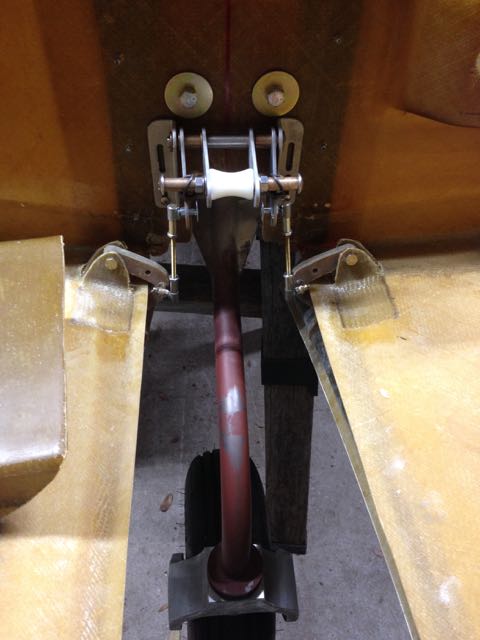
The lower hard point for mounting the gas spring was placed where the manual specified, but in this location the shock strut contacts the bottom of the gas spring when the nose landing gear is retracted.  I decided to move the bottom gas strut mounting post aft by one inch.  This necessitated extending the plywood hard point aft.  The old hard point was cut in half and the aft half removed, and then a new plywood hard point was glued in with structural epoxy, filleted with cabo, and then covered with 2x BID.  After this cured, the new hole and countersink for the gas strut post was drilled and the gas strut was installed. There was very little change in the over-center pressure (it was actually increased) after this modification, and now the nose landing gear can retract without mechanical interference all the way to the limits of the actuator cylinder.

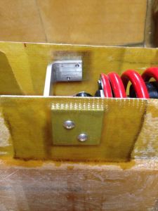
I also beefed up the nose landing gear over-center bracket  attach points with 2″ aluminum hard points glassed in to the keel side wall.  Just in case the actuator travel limits get out of adjustment, it will be harder for the hydraulic system to damage this part of the keel.  Its only thin fiberglass, and looks like it needs reinforcing anyway.

img_3749

Main landing gear and doors

(Assist from Cindy – Thanks!)

Side window mating faces were ground, and side windows were glued in place. MLG legs were reinstalled and over center linkage was installed and gear pockets were adjusted so that legs were spaced evenly with centerline.  Cabo was filleted around gear sockets to adhere them to the gear pockets.  The door latching mechanisms were installed in both the pilot and copilot doors.

Piling stuff into the fuselage for shipment to Georgetown!

IMG_3497

Center wing spar and landing gear

Leveling and centering checked again, and then the center wing spar was glued into place with structural adhesive+flox+cabo and clamped. MLG legs were bolted into place and bushings glued on both ends. MLG were then removed again. Thick tapered layups of triax were applied to link MLG bulkhead, firewall, and center spar together.

Aft keel was cut down for -5 option, and carbon keel cap was placed in position (not glued). NLG linkage, shock absorber, and over center link was installed in keel. NLG swing check completed.  NLG bushings and over-center hard points were mounted inset in keel skin, so careful cutting of outer skin and foam was needed.

Rudder pedals were positioned and attached to canard bulkhead and linkage was attached to see-saw.

Topside layups joining winglets to wings applied and curing. Strap layups at spar bolts applied – wings and winglets are completed (for now)!!!

IMG_3492

Winglets and main landing gear

(Matt and Elise assist – Thanks!!)

Right winglet exterior layup installed.  Left winglet bottom fit on and clecoed in place.

Upper MLG legs wrapped with Al tape and waxed, ready to accept gear socket layups.  Six-ply triax layup wetted out on plastic and then draped over MLG upper legs. MLG cable pullies installed in front of gear bulkhead. Note that pulleys were installed wrong – cable guide tabs should be aft, in the cutout.


Nose landing gear doors

NLG door hinge tabs (8) were cut out of a thin fiberglass layup.  These were ground to fit the contour of the fuselage when bolted to the door hinges, and then fixed in place using 5-minute epoxy.  Once the epoxy set, excess was ground off and a 2-ply BID layup was placed around the hinge tabs.  The NLG door part was removed from the fuselage and cut into two halves.

Fuselage bulkhead placement

The lower half of the fuselage was leveled fore and aft and side to side, and then it was fixed in place in its cradle using Bondo. Working forward, the engine firewall, landing gear pockets, gear bulkhead, cable conduits, keel, and canard bulkhead (all pre-fabricated parts) were placed in their respective positions, trimmed where necessary to fit, and their positions marked on the fuselage. Holes were drilled through the bulkhead flanges and the fuselage inner skin for later clecos.

The area of the fuselage close to the NLG door hinges was protected with aluminum tape.  Next, the NLG door part was glued into place with wood sticks and hot glue.  The NLG door hinges were alined and spaced correctly using a piece of all-thread, and then cemented into place with resin+cabosil+flox (cabo/flox).

Nose gear doors

I used a jigsaw to cut out the hole in the lower fuselage where the nose landing gear doors will go.  An inset is molded into the fuselage in the right shape and location – care was take to leave an even flange around the opening. The NLG doors are supplied as one piece (to be separated later). These had to be sanded to fit the NLG opening with about 1/8″ clearance all around.  The jigsaw was used to cut out four NLG door hinges from a thick piece of fiberglass layup – slow, blade-dulling work.